Since this column began, it has discussed how a Linux driver writer can create various types of kernel drivers, by explaining the different kernel driver interfaces including TTY, serial, I2C and the driver core. It is time to move on now and focus on writing real drivers for real hardware. We start by explaining how to determine what kind of kernel driver interface to use, tricks to help figure out how the hardware actually works and a lot of other real-world knowledge.
Let's begin with a goal of making a simple USB lamp device work well with Linux. Editor Don Marti pointed out a neat device, the USB Visual Signal Indicator, manufactured by Delcom Engineering and shown in Figure 1. I have no relationship with this company; I just think they make nice products. This device can be ordered on-line from the Delcom Web site, www.delcom-eng.com. Don challenged me to get the device working on Linux, and this article explains how I did it.

Figure 1. Delcom's USB Visual Signal Indicator is a simple first USB programming project.
The first goal in trying to write a driver for a device is to determine how to control the device. Delcom Engineering is nice enough to ship the entire USB protocol specification their devices use with the product, and it also is available on-line for free. This documentation shows what commands the USB controller chip accepts and how to use them. They also provide a Microsoft Windows DLL to help users of other operating systems write code to control the device.
The documentation for this device is only the documentation for the USB controller in the lamp. It does not explicitly say how to turn on the different color LEDs. For this, we have to do a bit of research.
After opening up the lamp device, making sure not to lose the spring that easily pops out when unscrewing the device, the circuit board can be inspected (Figure 2). Using an ohmmeter, or any kind of device for detecting a closed circuit, it was determined that the three different LEDs are connected to the first three pins of port 1 on the main controller chip.
In reading the documentation, the USB command to control the levels of the port 1 pins is Major 10, Minor 2, Length 0. The command writes the least significant byte of the USB command packet to port 1, and port 1 is defaulted high after reset. So, that is the USB command we need to send to the device to change the different LEDs.
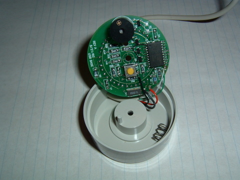
Figure 2. The three LEDs are connected to the first three pins of the controller chip.
Now that we know the command to enable a port pin, we need to determine which LED color is connected to which pin. This is easy to do with a simple program that runs through all possible combinations of different values for the three port pins and then sends the value to the device. This program enabled me to create a table of values and LED colors (Table 1).
Table 1. Port Values and the Resulting LED Patterns
Port value in hex Port value in binary LEDs on 0x00 000 Red, Green, Blue 0x01 001 Red, Blue 0x02 010 Green, Blue 0x03 011 Blue 0x04 100 Red, Green 0x05 101 Red 0x06 110 Green 0x07 111 No LEDs on
So, if all pins on the port are enabled (a value of 0x07 hex), no LEDs are on. This matches up with the note in the data sheet that stated, “Port 1 is defaulted high after reset.” It would make sense not to have any LEDs enabled when the device is first plugged in. This means we need to turn port pins low (off) in order to turn on the LED for that pin. Using the table, we can determine that the blue LED is controlled by pin 2, the red LED by pin 1 and the green LED by pin 0.
Since this column began, it has discussed how a Linux driver writer can create various types of kernel drivers, by explaining the different kernel driver interfaces including TTY, serial, I2C and the driver core. It is time to move on now and focus on writing real drivers for real hardware. We start by explaining how to determine what kind of kernel driver interface to use, tricks to help figure out how the hardware actually works and a lot of other real-world knowledge.
Let's begin with a goal of making a simple USB lamp device work well with Linux. Editor Don Marti pointed out a neat device, the USB Visual Signal Indicator, manufactured by Delcom Engineering and shown in Figure 1. I have no relationship with this company; I just think they make nice products. This device can be ordered on-line from the Delcom Web site, www.delcom-eng.com. Don challenged me to get the device working on Linux, and this article explains how I did it.
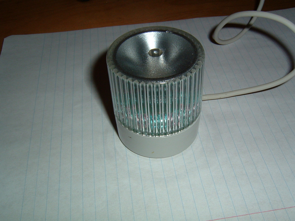
Figure 1. Delcom's USB Visual Signal Indicator is a simple first USB programming project.
The first goal in trying to write a driver for a device is to determine how to control the device. Delcom Engineering is nice enough to ship the entire USB protocol specification their devices use with the product, and it also is available on-line for free. This documentation shows what commands the USB controller chip accepts and how to use them. They also provide a Microsoft Windows DLL to help users of other operating systems write code to control the device.
The documentation for this device is only the documentation for the USB controller in the lamp. It does not explicitly say how to turn on the different color LEDs. For this, we have to do a bit of research.
After opening up the lamp device, making sure not to lose the spring that easily pops out when unscrewing the device, the circuit board can be inspected (Figure 2). Using an ohmmeter, or any kind of device for detecting a closed circuit, it was determined that the three different LEDs are connected to the first three pins of port 1 on the main controller chip.
In reading the documentation, the USB command to control the levels of the port 1 pins is Major 10, Minor 2, Length 0. The command writes the least significant byte of the USB command packet to port 1, and port 1 is defaulted high after reset. So, that is the USB command we need to send to the device to change the different LEDs.
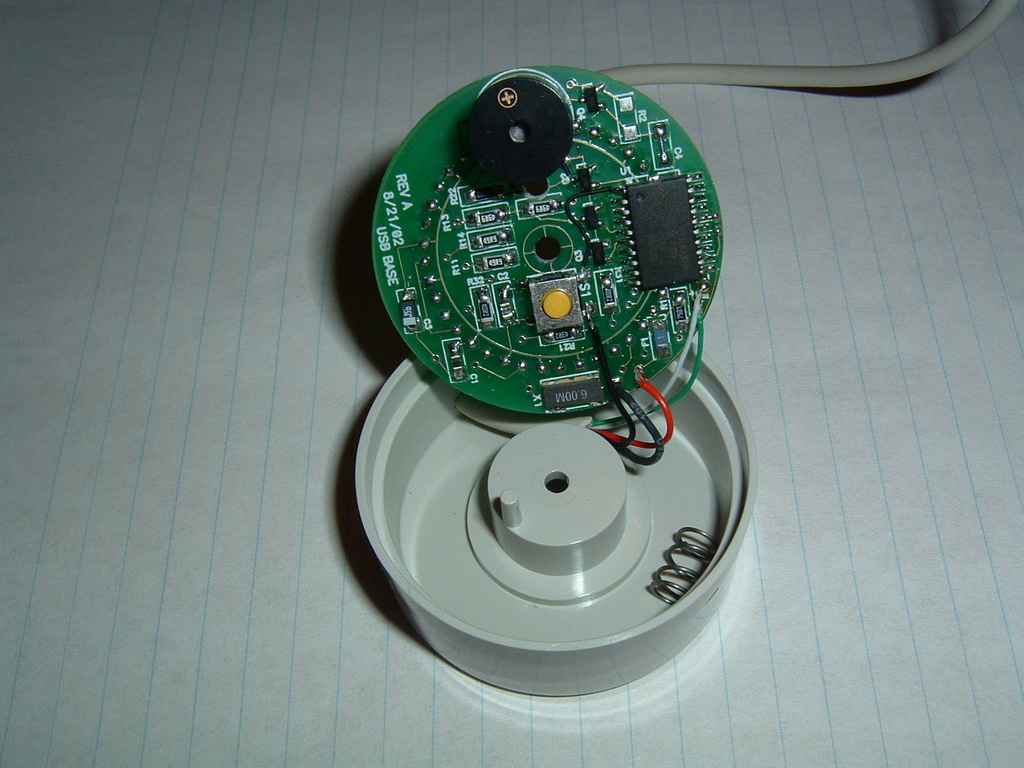
Figure 2. The three LEDs are connected to the first three pins of the controller chip.
Now that we know the command to enable a port pin, we need to determine which LED color is connected to which pin. This is easy to do with a simple program that runs through all possible combinations of different values for the three port pins and then sends the value to the device. This program enabled me to create a table of values and LED colors (Table 1).
Table 1. Port Values and the Resulting LED Patterns
| Port value in hex | Port value in binary | LEDs on |
|---|---|---|
| 0x00 | 000 | Red, Green, Blue |
| 0x01 | 001 | Red, Blue |
| 0x02 | 010 | Green, Blue |
| 0x03 | 011 | Blue |
| 0x04 | 100 | Red, Green |
| 0x05 | 101 | Red |
| 0x06 | 110 | Green |
| 0x07 | 111 | No LEDs on |
So, if all pins on the port are enabled (a value of 0x07 hex), no LEDs are on. This matches up with the note in the data sheet that stated, “Port 1 is defaulted high after reset.” It would make sense not to have any LEDs enabled when the device is first plugged in. This means we need to turn port pins low (off) in order to turn on the LED for that pin. Using the table, we can determine that the blue LED is controlled by pin 2, the red LED by pin 1 and the green LED by pin 0.
No comments:
Post a Comment